| |
|
|
| |
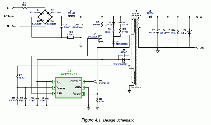
5V 1A charger circuit schematic
diagram


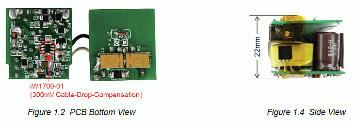
This document provides a reference design for a universal
input 5V 1A Mini-TA Charger circuit isolated flyback power
supply. For this design the iW1700-01 is used. This document
contains the complete specification of the power supply, a
detailed circuit schematic diagram, an entire bill of materials
required to build the power supply, a drawing of the power
transformer, and test data of the most important performance.
AC input range 90-264VAC
DC output 5V 1.00–1.20A (CC)
Meet “ZeroPower” no-load standby power consumption
requirement
|
|