|
|
Note, on
modern Volkswagen Group cars and some older vehicles (such as the
Peugeot 106 or Vauxhall Astra) the +12V Ignition and Battery positions
are reversed.
Attention:
The connector
wiring may vary depending on the car manufacturer, even when ISO
connectors are used. We recommend to check the car’s wiring provision
before connecting the car stereo.
Please pay
particular attention to pin 5, where a misconnection might cause
damage to the car or radio.
Take special care
when installing into ’98 or later VW/Audi/Skoda/Seat models as there
may be a 12 V connection on Pin 5, which could damage the car stereo or
into Ford from ’97 or later , with an ISO connector, on which damage
to the car’s microcomputers is possible if misconnected.
Use of ISO
connector adapters available on the market may facilitate
installation.
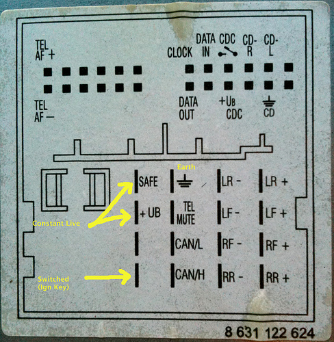
Power
(A)
The first connector A is always present, is usually black in colour,
and contains pins for power-supply, off/on (typically controlled by
ignition key), optional control for a motorised antenna and so on.
- On some
cars the +12V Ignition and Battery positions are reversed, such
as later Volkswagen
group cars, Peugeot
106, Vauxhall Astra, Citroën
C3.
- Pin 1 is optional; used for
speed dependent volume control and possibly navigation.
- Pin 2 is optional; used for
reversing lamp signal on Becker radios with navigation.
- Pin 3 is also used for phone
mute (Becker)
- Pin 6 is optional; used for
vehicle instrument illumination
Loudspeaker (B)
The second connector B is for connecting four loudspeakers,
front, rear, left and right, and is usually brown in colour.
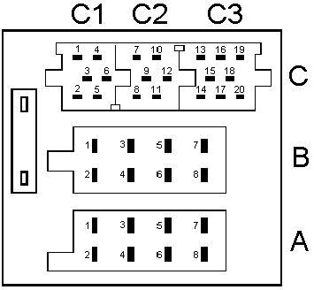
Miscellaneous (C)
The connector C is optional. Some times, it appears as one 20-pin
connector, often red in colour, or it may be divided into three
separate connectors which may be hooked together, in which case C1
is usually yellow, C2 is usually green which C3 is usually blue in
colour. The contact spacing is narrower than the other connectors,
so the C connector is sometimes referred to as mini-ISO.
Note: ISO 10487 only defines the physical attributes
of the connectors, not the
pin/signal designations, which are manufacturer-defined.
The example above is oriented towards VW vehicles only.
ISO
10487
je
standardi
8-pinski
konektor koji se koristi kod autoradio uređaja (head unit). Ima
kontakte za napajanje, off/on ( kontroliran ključem za paljenje), za
zvučnike i automatsku antenu.
|
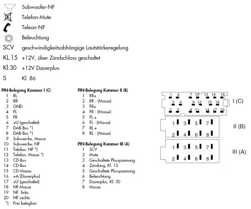
ISO Konektor A napajanje |
|
PIN 1 -
GALA
Geschwindigkeitsabhängige
Lautstärkeranpassung – or SCV speed-dependent
volume control.
Ovaj pin se koristi u nekim autoradio uređajima za automatsko
pojačanje glasnoće zvuka. Potreban mu je izlaz sa senzora brzine.
Napomena: ako mjerač brzine prestane raditi kad je autoradio
spojen, tada je taj pin vjerojatno uzemljen jer radio vjerojatno
koristi taj pin za neku drugu funkciju osim za GALA. |
|
PIN 2 -
Mute control
– ovaj pin služi za stišavanje zvuka autoradia, uzemljuje ga neka
druga vanjska komponenta npr. mobilni telefon koji je spojen na
autoradio. |
|
PIN 3 –
RFLS
Ruckfahrtlichtschalter - the reversing light switch. Satelitska
navigacija koristi ovaj signal, GALA signal (pin 1) i unutarnji
laserski žiroskop za izračunavanje u odsustvu satelitskog signala.
+12V ulaz na autoradiu s uključenim kontaktom na bravi za paljenje
i auto je u brzini za kretanje unazad. |
|
PIN 4
– stalnih +12V s akumulatora - napajanje za autoradio.
Povezivanjem autoradija direktno na akumulator, nije potrebno
imati ključ u bravi za paljenje. Neki moderni autoradio uređaji
imaju automatsko isključivanje. Na ovaj priključak spaja se
memorija autoradia. |
|
PIN 5
– Automatska antena – izlaz iz autoradia +12V maksimum 150
– 300mA za napajanje automatske ili elektronske antene. Ako
postoji mora se spojiti iako antena nije automatska. On također
upravlja zvučnim signalom koji upozorava da su vrata otvorena. |
|
PIN 6
– osvjetljenje +12V ulaz na autoradiju kad su svjetla upaljena.
Kod nekih autoradia on zapravo osvjetljuje display – kod drugih
može zatamniti osvjetljenje, zamjenjuje odnos crno na bijelo ili
čak mijenja boju od zelene do narančaste. Ako tabla s
instrumentima u automobilu ima funkciju regulacije osvjetljenja,
taj pin treba spojiti kako bi se moglo regulirati jačina
osvjetljenja. Žica od osvjetljenja upaljača za cigarete se može za
to koristiti. |
|
PIN 7 –
+12V sa ključa za paljenje kad je ključ u kontakt bravi na
položaju ON ili ACC. |
|
PIN 8
– uzemljenje, šasija, minus 12V |
|
ISO Konektor B
-
zvučnici |
|
·
Pin 1
- Right rear speaker + zadnji desni zvučnik +
·
Pin 2
- Right rear speaker - zadnji desni zvučnik -
·
Pin 3
- Right front speaker + prednji desni zvučnik +
·
Pin 4
- Right front speaker - prednji desni zvučnik -
·
Pin 5
- Left front speaker + lijevi prednji zvučnik +
·
Pin 6
- Left front speaker - lijevi prednji zvučnik -
·
Pin 7
- Left rear speaker + lijevi zadnji zvučnik +
·
Pin 8
- Left rear speaker -
lijevi zadnji zvučnik -
|
|
Konektor B se koristi samo za zvučnike. Koja žica ide na koji
zvučnik može se lako utvrditi s baterijom od 1,5V. Zvučnik će
kliknuti i vidjet ćete pomicanje membrane unaprijed ili unazad.
Zvučnici moraju biti pravilno fazirani (pazite na + i – pol na
zvučniku) jer u suprotnom ćete imati slab bas. Žice za zvučnik su
u paru, žica s prugom je + pol zvučnika. |
|
C1 - external amplifier or
equaliser |
|
-
Pin 1
- Line out left rear
-
Pin 2
- Line out right rear
-
Pin 3
- Line out ground
-
Pin 4
- Line out front left
-
Pin 5
- Line out front right
-
Pin 4
- +12v switched - maximum 150mA
|
|
C2 - remote control |
|
-
Pin 7
- RXD
-
Pin 8
- TXD
-
Pin 9
- Chassis ground
-
Pin 10
- +12v switched - maximum 150mA
-
Pin 11
- Remote control in
-
Pin 12
- Remote control ground
|
|
C3 - CD changer |
|
-
Pin 13
- CDC data in (bus)
-
Pin 14
- CDC data out
-
Pin 15
- CDC +12v permanent
-
Pin 16
- CDC +12v switched - maximum 300mA (+A)
-
Pin 17
- CDC data ground (+U)
-
Pin 18
- CDC audio frequency ground
-
Pin 19
- CDC audio frequency left
-
Pin 20
- CDC audio frequency right
|
|
ISO konektor C
|
|
Konektor C su zapravo tri odvojena konektora koja su užlijebljena
zajedno. On nije uvijek prisutan, ponekad samo dio postoji. Obično
je priključen na uređaj kojeg podržava. |
|
|
| |
Car radio
connectors
ISO2
factory
(OEM) FAKRA
After
2000,
some
companies began to
apply the
new standard
connector.
It has now become
almost
standard
because
it
spun off
a separate
division.
This type of
connector
is listed
under the name
FAKRA.
It is a
connector
that uses
the CAN bus.
Many
signals are
transmitted
on
the
bus.
They are:
- Information on
the ignition
- Information about the
lights on
- Information on
speed
The next
step is to
transfer
control information
and
audio signals
in digital form
by means of
fiber optic line.
The
connector
FAKRA
is
space for two
optical fibers
transmitting
and two
receiving.
With the introduction of
this type of
connector
antenna connectors
have been changed.
Quadlock
From 2000 and onwards, manufacturers, such as BMW,
Citroen, Ford, Mercedes Benz, Peugeot, Volkswagen, Rover, Audi,
Seat, Opel and Škoda have started using a 40 pin connector instead,
called the Quadlock (or Fakra, after the manufacturer).
The Quadlock connector consists of a block of 16
flat pins analogous to the two main ISO 10487 connectors. While the
physical contact pins are the same, the pin allocation is not
entirely the same, and the connector housing is not compatible. In
addition to the 16 pins, like ISO 10487, there are minor connectors
for optional equipment. They fit within the frame of the main
connector, and has coding so that they cannot be interchanged. Minor
connector B has 12 pins for audio output signals. Minor connector C
has 12 pins for various audio sources such as CD-changers, MP3
players.
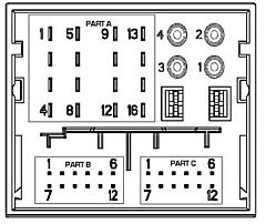
Quadlock A
|
1) right rear + |
5) right rear - |
|
9) I-bus (BMW) |
13) antenna (out) |
|
2) right front + |
6) right front - |
|
10) phone mute |
14) illumination |
|
3) left front + |
7) left front - |
|
11) tel on |
15) 12V battery |
|
4) left rear + |
8) left rear - |
|
12) ground |
16) 12V switched |
AUDI RNS-E
Aisin
|
Pin |
Main connector |
connector A (CD-C) |
connector B |
| 1 |
- |
MOST Ring break |
MIC IN - |
| 2 |
Speaker RF+ |
cd-changer line in gnd |
RFLS (wsteczny) |
| 3 |
Speaker
LF+ |
V-signal |
line out FL |
| 4 |
- |
cd-changer +12V |
MIC OUT - |
| 5 |
- |
K-line |
line out RL |
| 6 |
SpeakerRF- |
cd-changer data out |
telefon in - |
| 7 |
Speaker
LF- |
BOSE pin |
MIC IN + |
| 8 |
- |
cd changer line in L+ |
line out GND |
| 9 |
CAN H |
cd changer line in R+ |
line out FR |
| 10 |
CAN L |
cd-c +12V ster. |
MIC OUT + |
| 11 |
mute |
cd-changer data in |
line out RR |
| 12 |
masa |
cd-changer clock |
telefon in + |
| 13 |
amplifier remote |
x |
x |
| 14 |
DWA-GND |
x |
x |
| 15 |
+12V |
x |
x |
| 16 |
+SAFE |
x |
x |
Fakra to iso adapter
|
|