| |
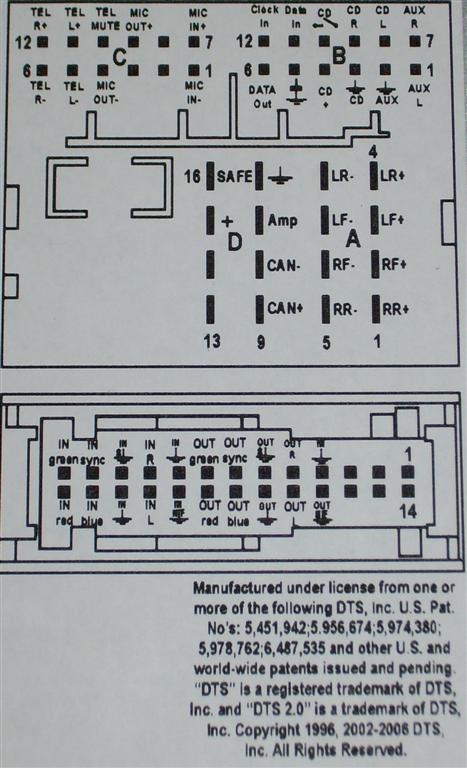
RCD510
1. Aerial Connector
DAB aerial input connection, optional
or SDARS aerial input connection for vehicles
for USA and Canada
2.
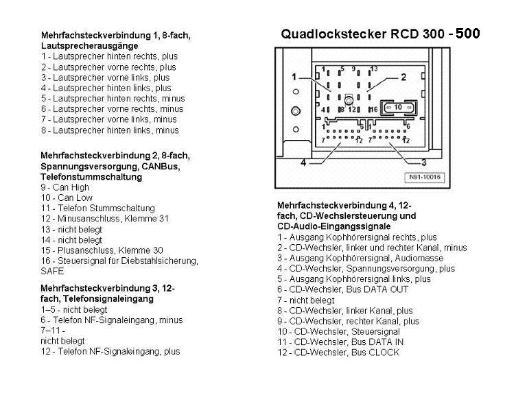
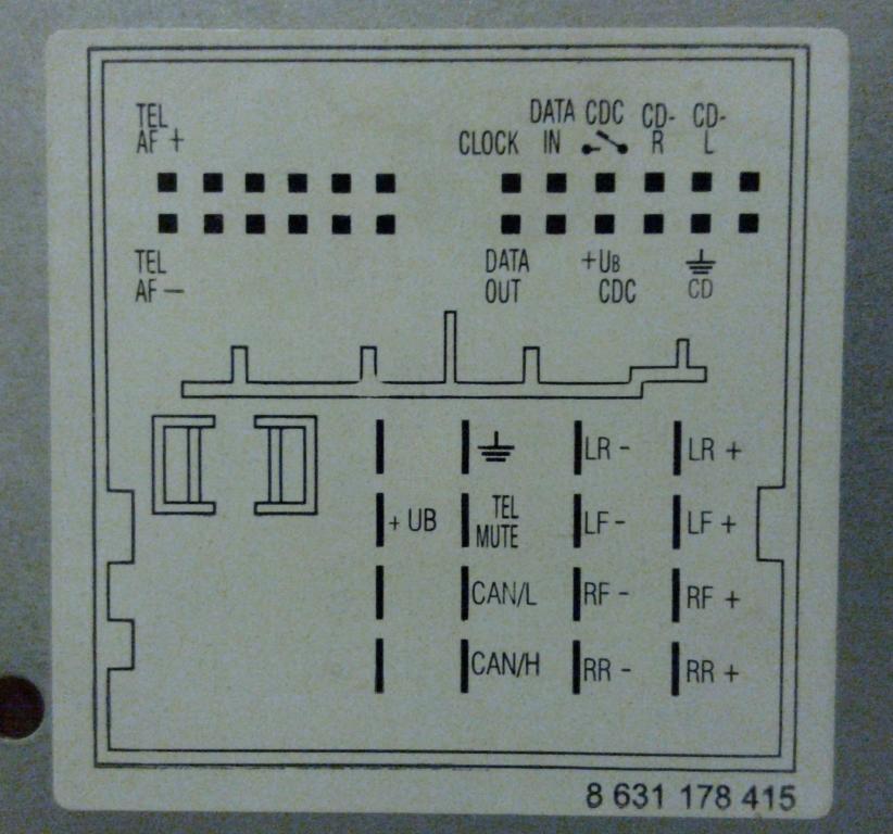
Multi-pin connector 1, 8-pin, for loudspeaker outputs
1 – Rear right loudspeaker, positive
2 – Front right loudspeaker, positive
3 – Front left loudspeaker, positive
4 – Rear left loudspeaker, positive
5 – Rear right loudspeaker, negative
6 – Front right loudspeaker, negative
7 – Front left loudspeaker, negative
8 – Rear left loudspeaker, negative
3.
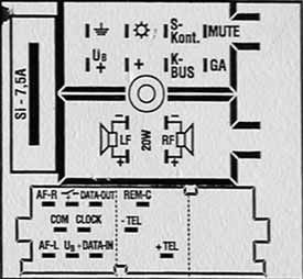
Multi-pin connector 2, 8-pin, for voltage supply
lines and CAN bus
9
– CAN bus, high
10
– CAN bus, low
11
– Display voltage supply, positive
12
– Voltage supply, negative, terminal 31
13
– Display HV CAN bus low
14
– Display HV CAN bus high
15
– Voltage supply, positive, terminal 30
16
– Anti-theft coding control signal, SAFE, positive
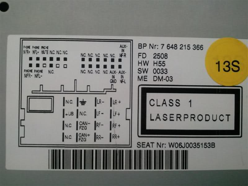
4. Multi-pin connector
3, 12-pin, for telephone and microphone signals
1
– Microphone input, negative
2
– AUX output, audio, right
3
– AUX output, common signal earth
4
– Microphone output, negative
5
– Telephone audio input signal left, negative
6
– Telephone audio input signal right, negative
7
– Microphone input, positive
8
– AUX output, audio, left
9
– Microphone output, positive
10
– Telephone mute (mute switch for radio)
11
– Telephone audio input signal left, positive
12
– Telephone audio input signal right, positive
5. Multi-pin connector 4, 12-pin, for CD
changer control and CD audio input signals
1 –
AUX signal input, left
2 – AUX signal earth
3 – CD changer, audio signal earth
4 – CD changer, voltage supply, positive, terminal 30,
contact continuous load greater than 1 A, temporary peak
load 5 A
5 – Not assigned
6 – CD changer, DATA OUT
7 – AUX signal input, right
8 – CD changer, left audio channel, CD/L
9 – CD changer, right audio channel, CD/R
10 – CD changer, control line, switched positive
11 – CD changer, DATA IN
12 – CD changer, CLOCK (internal check protocol for
data flow monitoring)
6. Multi-pin connector 5, audio
and video, 26-pin
(this will only be fitted to models
fitted to vehicles with RVC factory fitted or ordered
through spare parts with the RVC input option)
1 –
Reserved for Debug RX protocol
2 – Reserved for Debug TX protocol
3 – Not assigned
4 – Video signal input, RGBS, negative
(ground)
5 – Video signal output LF, Right (Audio use 17 for
ground)
6 – Ground Sync input
(Internal universal preparation for mobile
telephone, mobile telephone detection)
7 – Video signal output, vertical and horizontal
synchronisation(Internal universal preparation for
mobile telephone, cradle and button evaluation)
8 – Video signal ouput, green
(Internal universal preparation for mobile telephone,
cradle, aerial diagnosis)
9 – Video signal input, RGBS, negative (ground)
10 – Video signal input LF, right (Audio use 24 for
ground)
11 – Video signal input, screening earth
12 – Video signal input, vertical and horizontal
synchronisation
13 – Video signal input, green
14 – Not assigned
15 – Not assigned
16 – Not assigned
17 – Video signal output, LF, negative (ground)
18 – Video signal output LF, Left (Audio use 17 for
ground)
19 – Video signal output, RGBS, negative (ground)
(Internal universal preparation for mobile telephone,
cradle, negative)
20 – Video signal output, Blue
(Internal universal preparation for mobile telephone,
switched terminal 30)
21 – Video signal output, Red
22 – Video signal input, LF, negative
23 – Video signal input, LF, left (Audio use 24 for
ground)
24 – Video signal input, RGBS, negative (ground)
25 – Video signal input, blue
26 – Video signal input, red
7. Aerial Connector
AM/FM
aerial input connection
8. Aerial Connector
FM 2
aerial input connection
|
|