| |
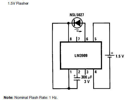
1.5V battery cell LED flasher
circuit diagram
Download:
1.3V IC Flasher, Oscillator, Trigger or Alarm
LM3909
LED flasher circuit diagram 1.5V battery cell 1.3V IC Flasher,
Oscillator, Trigger or Alarm. Most linear integrated circuits are
designed to operate with power supplies of 4.5 to 40V. Practically
no battery/portable equipment is provided with indicator lights due
to unacceptable power drain. Even LEDs (solid state lamps) won't
light from a 1.5V battery, and drain the common 9V radio battery in
a few hours. The LM3909 changes all this. Obtaining long life from a
single 1.5V cell, it opens a whole new area of applications for
linear integrated circuits.
Sufficient voltage for flashing a light emitting diode is
generated with cell voltage down to 1.1V. In such low duty cycle
applications batteries will last for months to years of continuous
operation. Such flasher circuits then become practical for marking
location of flashlights, emergency equipment, and boat mooring
floats in the dark. The LM3909 is simple in design, easy to use, and
includes extra resistors to minimize external circuitry and the size
of the completed flasher or oscillator. The LM3909, although
designed as a LED flasher, is ideal for other applications such as
high current, trigger pulse for SCRs and ``Triacs.'' The frequency
of oscillation adjusts from under 1 Hz to hundreds of kHz. Waveshape
can be set from pulses a few ms wide to approximately a square wave.
Thus the LM3909 can perform as a sound effects generator, an audible
alarm, or audible continuity checker. Finally it can be a radio (detector/amplifier),
low power one-way intercom, two-way telegraph set, or part of a
``mini-strobe'' light flashing up to 7 times per second. Operating
with only a 1.5V battery as a supply gives the LM3909 several rather
unique characteristics. First, no known connection can cause
immediate destruction of the IC. Its internal feedback loop insures
self-starting of properly loaded oscillator circuits. Experimenters
can safely explore the possibilities of the LM3909 as an AC
amplifier, one-shot, latch circuit, resistance limit detector, multi-tone
oscillator, heat detector, or high frequency oscillator. With the
accent on the practical, a brief circuit description will be given
followed by circuits in the following application areas: Flasher &
Indicator Applications Audio & Oscillator Applications Trigger &
Other Applications For those who want to modify or design their own
circuits using the LM3909, application hints will be covered near
the end of this note.
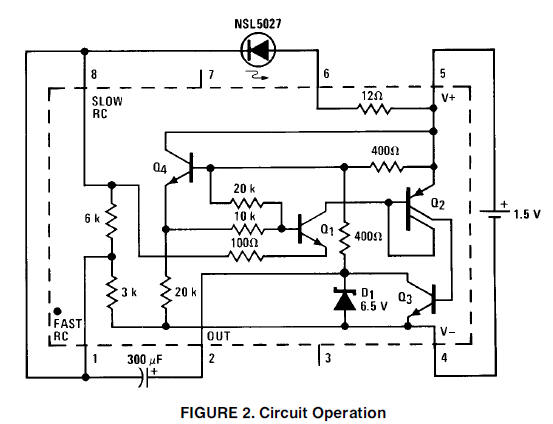
CIRCUIT DESCRIPTION The circuit of Figure 2 again shows the
typical 1.5V LED flasher, but with the internal circuitry of the IC
illustrated. The flasher achieves minimum power usage in two ways.
Operated as above, the LED receives current only about 1% of the
time. The rest of the time, all transistors but Q4 are off. The 20k
resistor from Q4's emitter to supply-common draws only about 50 mA.
The 300 mF capacitor is charged through the two 400X resistors
connected to pin 5 and through the 3k resistor connected to pin 1 of
the circuit.
Transistors Q1 through Q3 remain off until the capacitor becomes
charged to about 1V. This voltage is determined by the junction drop
of Q4, its base-emitter voltage divider, and the junction drop of
Q1. When voltage at pin 1 becomes a volt more negative than that at
pin 5 (supply positive terminal) Q1 begins to conduct. This then
turns on Q2 and Q3. The LM3909 then supplies a pulse of high current
to the LED. Current amplification of Q2 and Q3 is between 200 and
1000. Q3 can handle over 100 mA and rapidly pulls pin 2 close to
supply common (pin 4). Since the capacitor is charged, its other
terminal at pin 1 goes below the supply common. The voltage at the
LED is then higher than battery voltage, and the 12X resistor
between pins 5 and 6 limits the LED current. Many of the other
oscillator circuits work in a similar fashion. If voltage boost is
not needed (with or without current limiting) loads can be hooked
between pins 2 and 6 or pins 2 and 5. |
|
