|
Download:
555 Holiday
Fun
Making Things Blink 1: lighting up an LED.
6. 3. Making Things Blink 2: the 555Timer IC.
8. 4. Making Things Pulse. 10. 5. Making Things Blink 3:
counting with ...
555 Circuits.pdf
The 555 is
also available as a CMOS chip (ICM7555
or ICL7555 or TLC555)
.... a circuit
diagram (such
as 100p on a circuit and
101 on the capacitor or 10 on a ...
Dual LED Flasher
Using a 555
Timer
1. Dual LED Flasher
Using a 555
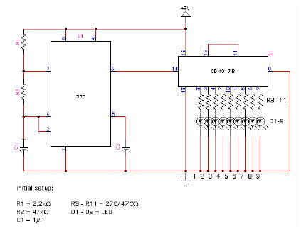
Timer. Explanation: R1, R2, R3, C1, and the supply
voltage determine the flash rate. The lower the value of R1,
R2, R3, and C1 ...
Dialight 555-2001
Datasheet
COLOR. GENERAL PURPOSE. 555-2001.
Red. 555-2301.
Green. 555-2401.
Yellow ... See Page 3-17 and 3-18 for Reference Only LED Drive Circuit Examples.
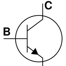
555 Based Timer
555 Timer IC
ii. Wires iii. Power Supply of +5V DC. Black wire is GND and
Brown wire is +5V. iv. LED. LED has
two terminals and the shorter terminal should be ...
LM555 Timer (Rev.
D)
Schematic Diagram. 1. An IMPORTANT NOTICE at the end of this
data sheet addresses availability, warranty, changes, use in
safety-critical applications,.
PCB Wizard - Tutorial 2
View how the finished PCB will look. Components. To make this circuit you
will need: 8-pin dual-in-line (DIL) socket. 555
timer integrated circuit (IC).
Red LED.
Project
pushed, the astable 555
timer oscillates
and causes the IR LED to
emit a modulated, or pulsed, infrared signal. This signal is
received via our receivercircuit's ...
Make Magazine's “555 Timer”
Thus. the 555 timer was
born. that stands on eight metal legs spaced 1/1o" apart.
... 555
CIRCUIT BEGINNING:
This is how the LED-flasher circuit in
Figure 2 ...
|
