Flash LED circuit diagram
Download:
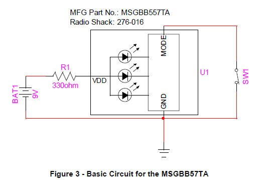
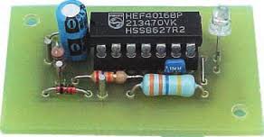
MSGBB557TA – 7 Color Blinking
LED Circuit Setup and
Usage
MSGBB557TA – 7 Color Blinking
LED Circuit Setup and
Usage. By Sean D. Liming. Managing Director. SJJ Embedded Micro
Solutions.
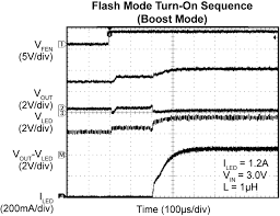
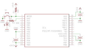
1.2A High-Brightness Flash
LED Driver with Single-Wire
Serial ...
The
MIC2873 is a high-current, high-efficiency flash
LED driver. The LED .... LED Short-Circuit ....
Simplified MIC2873 Functional BlockDiagram.
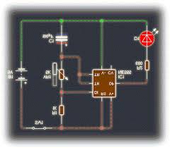
LM3909 LED
Flasher/Oscillator
LED while
operating on a supply of 1 5V or less The circuit ... and a small 3V
rated part will be suitable for any LED
flasher using a supply
... Schematic Diagram.
LABORATORY
10: DISPLAYING A 7-SEGMENT LED AND ...
Program the 8255 to flash an LED array.
... Figure L10.2 shows the 7-segmentLED decoder
circuit. With this ... A schematic
diagram is provided below
to show.
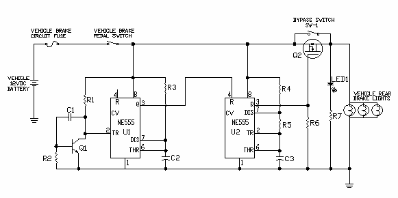
BRAKE
LIGHT FLASHER CIRCUIT
circuit uses a Motorola ...
The circuit causes
the automobile brake lights to flash at
about 3 times per second for 1-1/2 to 2 ... schematic and
parts list.) SW! is installed so ... This LED monitors circuit operation
and should be mounted on the rear speaker deck where it is ...
Forever Flasher
Interactive Inc and Wimborne Publishing Ltd make no
warranties of any kind, ... micropower l.e.d.
flasher circuit may ...
The full circuit diagram for
the Forever.
Project 1 Hello World -
Turning on a LED
Assuming a LED drop
of 1.5 V,. LED_Current = ... Figure 1 Schematic
Diagram- Hello World ... CW1 and CW2, which are present in Flash program
memory.
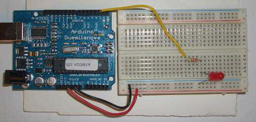
Arduino
Microcontroller Guide
of an LED and
its symbol used in electronic schematics.
Using 22 g ... Now try this program, which will flash the LED at
1.0 Hz. Everything after the // on a line is a.
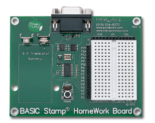
BASIC
Stamp Guide
And
here is a schematic of
the HomeWork with a description of its parts taken .... Now try this
program which will flash the LED at
1.0 Hz. The lines beginning with ...
Livewire
- Tutorial 2 - New Wave Concepts
components at the start can help produce a
much neater circuit
diagram. ... frequency (f) of 0.14 Hz (Hertz) which would result in
the LED flashing about.
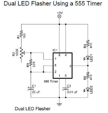
Dual LED
Flasher Using a 555 Timer
Explanation: R1, R2, R3, C1, and the supply
voltage determine the flash rate.
... cycle of the circuit (the
time LED 2
is on divided by the period of the cycle.
|
