Linear LED driver circuit diagram
30V adjustable current
Download source:
30V, ADJUSTABLE CURRENT SINK LINEAR LED
DRIVER AL5802 - Diodes, Inc.
Applications: Linear LED driver LED signs Offline
LED luminaries The AL5802 open-collector output can operate from
0.8V to 30V enabling it to operate from 5V to 24V power supplies
without additional components ADJUSTABLE CURRENT SINK LINEAR LED
DRIVER. Linear LED driver circuit diagram 30V adjustable current
AL5802 has been designed for driving low current LEDs with typical
LED current of 20mA to 100mA. It provides a cost effective way for
driving low current LEDs compared with more complex switching
regulator solutions.
Furthermore, it reduces the PCB board area of the solution as
there is no need for external components like inductors, capacitors
and switching diodes.
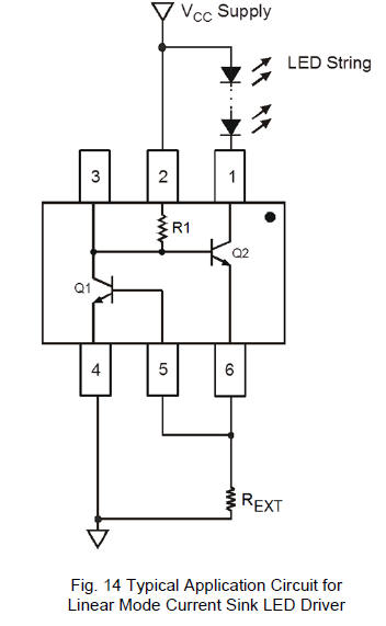
Figure 14 shows a typical application circuit diagram for driving
an LED or string of LEDs. The NPN transistor Q1 measures the LED
current by sensing the voltage across an external resistor REXT. Q1
uses its VBE as reference to set the voltage across REXT and
controls the base current into Q2. Q2 operates in linear mode to
regulate the LED current. The LED current is ILED = VBE(Q1) / REXT
From this, for any required LED current the necessary external
resistor REXT can be calculated from REXT = VBE(Q1) / ILED |
