Non-Isolated LED Lighting circuit
diagram Off-Line Switcher
Download:
LYT0002/0004-0006 LYTSwitch-0 Off-Line Low
Power LED Driver IC Family - Power Integrations, Inc.
Non-Isolated LED Lighting circuit diagram Off-Line Switcher, 6
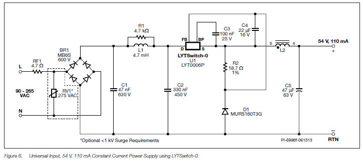
W (Output) Universal Input Buck LED Driver Converter The circuit
shown in Figure 6 is a typical implementation of a non-isolated,
power factor corrected buck power supply for LED driver applications.
The simplicity and low component count make this ideal for space
constrained, cost sensitive designs such as GU10 or A19 size lamps.
This design was optimized to drive an LED string at a voltage of 54
V with a constant current of 110 mA, giving 6 W of output power. The
design operates over a universal input range from 90 VAC to 265 VAC
and achieves an output current tolerance of < ±5% at nominal line
voltage.
The input capacitance (C1 + C2) was reduced to achieve the
highest possible power factor input Figure 5. Frequency Jitter. 600
0 20 68 kHz 64 kHz VDRAIN Time (μs) PI-3660-081303 500 400 300 200
100 0 while still meeting conducted EMI limits. Power factor is >0.5
at 230 VAC and >0.7 PF at 120 VAC meeting requirements for LED lamps
in Europe and USA.
The input stage comprises fusible resistor RF1, bridge rectifier
BR1, capacitors C1 and C2, and inductor L1. Resistor RF1 is a flame
proof, fusible, wire wound resistor. It accomplishes several
functions: a) Inrush current limitation to below specification of
BR1; b) Differential mode conducted EMI noise attenuation; c) Fuse
should any other component fail short-circuit; d) Higher power
factor. Capacitor C1, C2 and inductor L1 forms a π filter to reduce
differential mode EMI. Capacitor C2 provides local decoupling for
the switching current through U1. There is an optional parallel
resistor on the board across L1 which damps the resonance of the pi
filter. The power processing stage is formed by the integrated
MOSFET switch within LYT0006 (U1), a free-wheeling diode (D1), sense
resistor (R2), power inductor (L2) and output capacitor (C5). To
reduce reverse recovery losses in D1 the value of L2 was designed
such that the converter operates in mostly discontinuous conduction
mode. Diode D1 is an ultrafast diode with a reverse recovery time (tRR)
≈35 ns. This recovery is recommended due to the high ambient
operating time temperature which will increase diode reverse
recovery charge.
A bobbin based EE10 core size indictor was selected for L2 in
order to prevent changes in inductance value when placed inside a
metal enclosure. Lower cost drum core or dog bone inductor types may
also be used, however these have an open magnetic path which can be
shorted by a metal enclosure. This reduces the effective inductance
and requires the value to be adjusted to take this into account when
placed inside the final enclosure.
Capacitor C5 is the output filter capacitor; its primary function
is to limit the output current ripple and ensures high frequency
currents flow within as small as a loop area as possible to reduce
EMI. Cost-Effective LED driver The LYTSwitch-0 family parts are a
highly integrated combination of controller, driver and switching
power MOSFET that enable low component-count, non-isolated switching
topologies for highly cost competitive LED lighting applications.
The LYTSwitch™-0 family is specifically designed for low cost LED
bulb replacement applications. LYTSwitch-0 devices integrate a 700 V
power MOSFET, oscillator, simple ON/OFF control scheme, a high-voltage
switched current source, frequency jittering, cycle-by-cycle current
limit and thermal shutdown circuitry into a monolithic IC. The
start-up and operating power are derived directly from the voltage
on the DRAIN pin. This eliminates the need for a bias supply and
associated circuitry plus allowing low-cost discrete inductors to be
used. The fully integrated auto-restart circuit in the LYTSwitch-0
family safely limits output power during fault conditions such as
short-circuit or open-loop, reducing component count and lower
system cost. |
