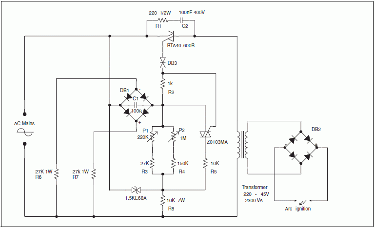
Arc welding transformer power regulation
schematic
Power variation schematic for arc welding transformer. The
schematic shows a typical circuit for welding equipment.
Potentiometer P2 is used for accurate control of the maximum turn-on
delay. DB1 diode bridge and R6-R7
resistors are used to discharge C1 at each line zero voltage. This
resets the voltage charge at each new half line cycle, and keeps the
same turn-on delay. The Transil reduces power dissipation through
both potentiometers.
Pulse-train triggering circuit

|