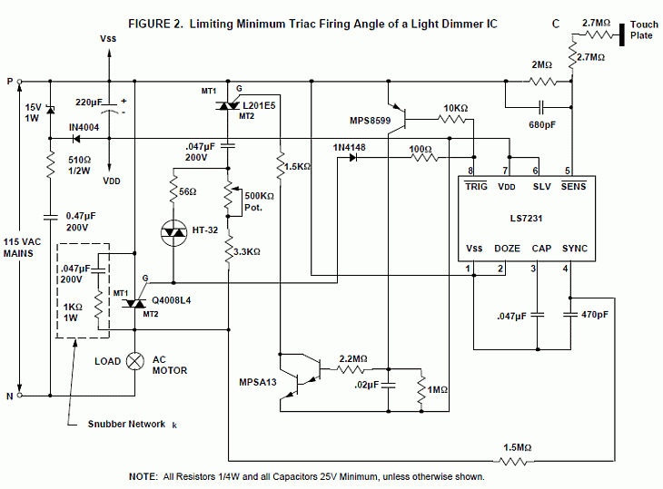
Dimmer AC motor speed control schematic
An electronic speed control for an AC Motor can be designed
with a Light Dimmer IC by limiting the minimum firing angle
of the triac so that the motor won’t stall. This can be done
effectively for high volume applications by making a minor
change to the IC.
An alternative to modifying the IC is illustrated in
Figure 2. Schematic shows how to control the Minimum Triac
Firing Angle so that it is greater than that determined by
the LS7231 Light Dimmer IC. The desired value of Minimum
Firing Angle is set by an Auxiliary Resistor-Capacitor-Diac
Circuit. When the IC produces trigger pulses at lower values
of firing angle, the Auxiliary Circuit fires the Triac. When
the IC produces trigger pulses at greater values of firing
angle, the IC trigger pulse fires the Triac. When the IC is
off, the Auxiliary Circuit is also off and the Triac does
not fire.
The major components required to implement this function
are the MPS8599 Transistor, MPSA13 Darlington, L201E5 Triac
and the HT-32 Diac.
 |