| |
VDO Car Radio Stereo Audio Wiring
Diagram Autoradio connector wire installation
schematic schema esquema de conexiones stecker konektor
connecteur
cable shema car stereo harness wire speaker pinout connectors
power how to install
|
|
| |
|
|
VDO CD9303UB-CV RDS
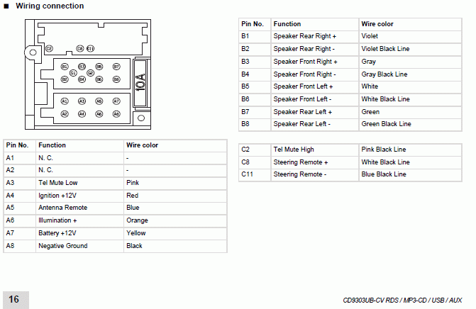
VDO TR7322
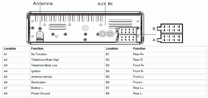
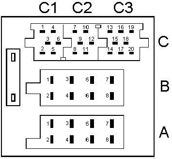
Siemens VDO models 22DC259 / 279 / 280
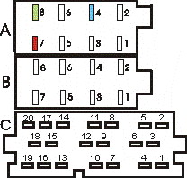
( A1 Speed) ( A2 NC) ( A3 Tel.Mute) ( A4
v.Permanentes +12) ( A5 Output +12 v) ( A6 Ilum) ( A7 v.Accesorios
+12) ( A8 GND)
( B1 + RR) (RR-B2) ( B3 + FR) ( B4 -FR) ( B5 + FL)
( B6 -FL) ( B7 + RL) ( B8 -RL)
( C1 sda display) ( C2 display scl) ( C3 display
mrq) ( C4 NC) ( C5 Radio on) ( C6 GND)
Original colors of yellow connector for the
display
( a Brown) ( 2 Green) ( 3 Orange) ( 4 NC) ( 5
White) (6 Lilac)
Another color version : ( 1 Red) ( 2 Violet with
brown) ( 3 Yellow) ( 4 Black) ( 5 green) ( 6 2 Black)
Siemens VDO CD 5104 CD5304
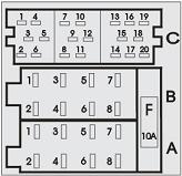
( A4 +12 V Direct) ( A5 Output +12 v.Antena.) ( A6
Lighting) ( A7 +12 V Accessories) ( A8 GND) ( B1 RR +) ( B2 RR-) (B3
RF +) ( B4 RF-) (B5 LF + ) ( B6 LF-) ( B7 LR +) ( B8 LR-) C1, C2,
C3, C4, C5 and C6 Remote.
| |
VDO Tunerlist,
VDO Updatelist
 |
|
| |
|
A |
Power connector |
|
1 |
Speed
Dependent Volume Control |
|
2 |
n/c |
|
3 |
Phone
mute (ground to activate) |
|
4 |
+12V
(constant) |
|
5 |
+
Aerial (12V when radio on) |
|
6 |
+
Lights (12V when lights on) |
|
7 |
+ACC
(12V when ACC on) |
|
8 |
GND |
|
B |
Speaker connector |
|
1 |
+ Rear Right |
|
2 |
-
Rear Right |
|
3 |
+
Front Right |
|
4 |
-
Front Right |
|
5 |
+
Front Left |
|
6 |
-
Front Left |
|
7 |
+Rear
Left |
|
8 |
-
Rear Left |
|
C1 |
CCU(*) connector |
|
1 |
DTA |
|
2 |
CLK |
|
3 |
MIRQ |
|
4 |
n/c |
|
5 |
Radio
ON |
|
6 |
GND |
|
C2
(**) |
AUX connector (**) |
|
7 |
n/c |
|
8 |
n/c |
|
9 |
n/c |
|
10 |
Audio
Left |
|
11 |
Audio
Right |
|
12 |
Audio
GND |
|
C3 |
CD Changer connector |
|
13 |
Tx (from HU to CDC or
PC) |
|
14 |
Rx (from PC or CDC to
HU) |
|
15 |
GND |
|
16 |
12V (constant) |
|
17 |
HU ON (12V when HU is
ON) |
|
18 |
SPDIF IN (***) |
|
19 |
SPDIF GND (***) |
|
20 |
(SPDIF GND) (***) |
|
|
| |
(*) Central Communication Unit. This is the
way the HU receives stalk control commands and sends
information to the dash display.
(**) Auxiliary input only available on Update
List models.
The AUX input must be activated in the head unit's menu. C2
doesn't exist at all on Tuner
List models
(***) Models before 2000 have an analog CD
Changer audio input instead of SPDIF. In that case, the
pinout is as follows: 18=Audio GND, 19=Audio Left and
20=Audio Right. |
|
| |
|
Car radio
|
Model autoradio |
Manufacturer |
MCU |
EEPROM |
IC Amplifier |
CD changer |
Car |
|
VDO |
22 RC260/65 |
VDO |
93CW44DF |
24C32 |
|
|
PEUGEOT |
|
VDO |
22 RC280/65 CD bez displeja |
VDO |
93CW44DF-3D89 |
24C32 |
|
|
CITROEN PICASSO |
|
VDO |
22 RC290 CD |
VDO |
93CW44DF |
24C32 |
|
|
OPEL |
|
VDO |
CDR2005 without display |
VDO |
P83CE560 |
24C16 |
|
|
|
|
VDO |
CDR500 without display |
VDO |
|
24C16 |
|
|
|
|
VDO |
|
VDO |
PN-R3-V1.01 93CW44DF-1B03(DC917X) |
24C32 smd |
|
|
|
|
|
| |
|
VDO |
CD 413 |
VDO |
87CM21F-5EB0 |
24C16 |
TDA7385 |
|
VDO |
CD 423 |
VDO |
|
|
|
|
VDO |
CD 423-24v |
VDO |
TMP87CM21F-5EB0 (BL-CD V1.0A) |
24C16 |
TDA7264 x 2 |
|
VDO |
CD 441 XED |
VDO |
TMP87PP21F 0142EAI |
24C16 |
TDA7384 |
|
VDO |
CD 531 B |
VDO |
TMP87PP21F 0104EA1 |
24C16 |
|
|
VDO |
CDR 2005(E) DC409/75 without display |
VDO |
P83CE560EFB055 |
24C16 smd |
TDA7375 x 2 |
|
VDO |
CDR 2005(E) DC409/75 without display |
VDO |
P83CE560EFB066 |
24C16 smd |
TDA7375 x 2 |
|
VDO |
CDR 2005(E) DC409/75 without display |
VDO |
P87CE560EFB701 |
24C16 smd |
|
|
VDO |
CDR 500(E) without display |
VDO |
P83CE560EFB055 or EFB069 |
24C16 |
TDA7375 x 2 |
|
VDO |
CR 169/80 |
VDO |
TMP47C820DF-3B27 |
24C02 |
HA13119 |
|
VDO |
CR 211 |
VDO |
TMP87PP21F |
24C14 |
|
|
VDO |
CR 213 |
VDO |
|
|
|
|
VDO |
CR 223 |
VDO |
|
24C16 |
TDA7375 |
|
VDO |
CR 223-24v |
VDO |
|
24C16 |
TDA7264 x 2 |
|
VDO |
CR 321 |
VDO |
87CP218F-3BV5 (VD02001V2.0) |
24C16 |
TDA7384A |
|
VDO |
CR 341 B |
VDO |
TMP87CP21BF-BV5 |
24C16 |
TDA7385 |
|
VDO |
CR 361 |
VDO |
TMP87PP21F |
24C16 |
TDA7384 |
|
VDO |
CR 441 X |
VDO |
|
|
|
|
VDO |
TR 114 only tuner |
VDO |
|
|
|
|
VDO |
TR 129/00 only tuner |
VDO |
47C8200F-3827 VER3.1 |
24C02 |
HA13119 |
|
VDO |
TR 124-24v only tuner |
VDO |
|
|
|
|
VDO DAYTON |
CD2200/00 panel |
VDO DAYTON |
93CW44DF-1A40 PI2kecon-R1.0 |
24C32 |
TDA7384 |
|
VDO DAYTON |
CD2201/00 panel 22 RC653/00 |
VDO DAYTON |
93CW44DF-1A40 PI2kecon-R1.0 |
24C32 |
TDA7384 |
|
VDO DAYTON |
CD2703 panel |
VDO DAYTON |
87CP21BF-4KES CD2703-R1.02 |
24C32 |
TDA7560 |
|
VDO DAYTON |
CD4502 panel |
VDO DAYTON |
SAFC161PI |
24C64 |
TDA7560 |
|
VDO DAYTON |
MS4150RS MULTIMEDIA NAVIGATION SYSTEM |
VDO DAYTON |
SAFC161CS32RF (SWV3.3V 19.6.00) |
24C32 smd |
TDA7454 |
|
VDO DAYTON |
MS4200 MULTIMEDIA NAVIGATION SYSTEM |
VDO DAYTON |
SAFC161CS32RF |
24C32 smd |
TDA7454 |
|
VDO DAYTON |
MS4200RS MULTIMEDIA NAVIGATION SYSTEM FD0403 |
VDO DAYTON |
SAFC161CS32RF (SWV3.3V 19.6.00) |
24C32 smd |
TDA7454 |
|
|
| |
VDO Car Radio Stereo Audio Wiring Diagram Autoradio connector
wire installation schematic schema esquema de conexiones stecker
konektor connecteur cable shema car stereo harness wire speaker
pinout connectors power how to install.
VDO Car radio wiring diagrams.
Car
radio wire diagram stereo wiring diagram gm radio
wiring diagram. Car stereo wiring diagrams car radio wiring car radio
wiring colors car radio wire car radio connections wiring diagram
car radio wire colours.
VDO auto radio wiring diagrams install car radio.
How to install car radio autoradio wiring harness stereo installation.
How to install car radio wires. Car radio
install car wiring diagrams wiring harness pinout connector diagram.
Car stereo radio
wiring diagram. How to wire a car radio wiring diagram for car stereo.
Car stereo wiring diagram radio installation head unit. Car radio
wire colors car audio wiring free radio wiring diagrams. Radio
diagram wiring car radio car radio wiring diagrams. Free car radio
wires stock diagram. Car radio wiring colour codes car
radio speakers.
|
|
| |
|
|
|