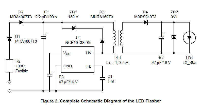
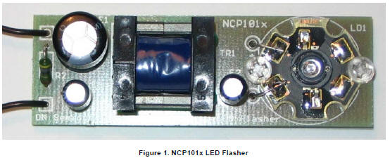
LED Flasher circuit diagram with
Luxeon V Star LED
Download:
NCP101x LED Flasher with Luxeon V Star LED
AND8224-D - ON Semiconductor http://www.onsemi.com/pub_link/Collateral/AND8224-D.PDF

LED Flasher circuit diagram with Luxeon V Star LED describes how to
easily design simple, isolated AC−DC converter for powering Luxeon V
Star LED in flashing mode.
Some examples are: warning lamps, emergency signs, beacon and so
on. In comparison with resistive or capacitive dropper with
electronic chopper is this solution more comfortable and features
some advantages such as: The monolithic power switcher, used in
this application, greatly simplifies the total design and reduces
time to production. The new line of the Power Switchers NCP1010 –
1014 is ideal for this purpose. This IC in the SOT−223 package
reduces size and is suitable for mass production. The output power
is given only by proper selection of this Switcher. The design
consists of safety resistor, rectifier with filtering capacitor,
power stage with switcher and transformer, output ultrafast
rectifier, output filtering capacitor and high power Luxeon LED. The
only component necessary for proper powering of the IC is the VCC
capacitor. The IC is directly powered from the HV Drain circuit via
internal voltage regulator. To eliminate the noise at the feedback
input, some small ceramic capacitor with value of around 1 nF is
necessary to be connected as close to the FB pin, as possible. As
the flash function is used special part of the safety circuitry of
the NCP101x Switcher. The timing of the flashing period is given by
the VCC capacitor E3. The duty cycle is fixed and is given by the
internal consumption of the IC.
Smaller Size, Lower Weight, Lower
Total Cost
Good Line Regulation, No Need of
Additional Linear Regulators
Efficient Design with up to 80%
Efficiency
Overload, Short Circuit and
Thermal Protected
Simple for Mass Production Thanks
to SMD Devices
Universal Design for Variety of LEDs – 1 W, 3
W, 5 W
 |