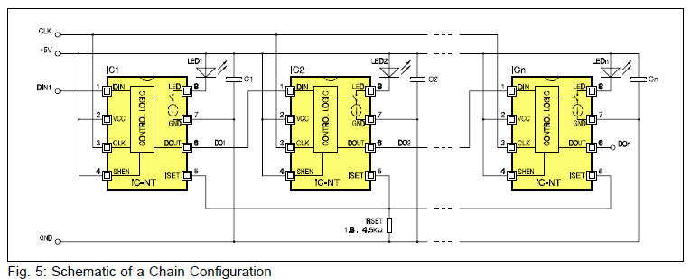
LED light chain circuit diagram
| |
Download: iC-NT
LIGHT CHAIN PULSE DRIVER
https://www.ichaus.de/upload/pdf/nt_a0es.pdf |
| |
|

Application: Electro-sensitive protective equipment (ESPE) ¨
Light curtain LED driver ¨ Light barrier LED driver
LED light chain circuit diagram iC-NT device is an LED pulse
driver for LED light barrier applications, especially LED light
chain circuitries. The device, which is controlled by a shift
register logic, features an adjustable LED current sink with a set
range of 0.4..1A (at room temperature).
For chain circuitries with several transmitters in operation, the
internal set of three flipflops enables a secure beam and data shift
control, free of race conditions. The decrease in LED efficiency
with a rise in temperature is almost compensated by a positive
temperature coefficient of the current sink. In order to generate
steep light pulses, the LED switch off is actively supported by the
discharge of its junction capacitance. The duration of this LED
short-circuiting is controlled by a monoflop. In the event of a
quick follow-up light pulse, a monoflop reset is performed
automatically to protect against cross currents.
The driver stage for the LED output prepares for a light pulse
when DIN reads a high signal; synchronized with the CLK leading edge,
the first flipflop transfers the DIN data to Q1 and powers up the
LED sink. Since the chain is loaded with just one single high bit
and DIN is given by the output DOUT of the previous device, input
DIN now reads low at the falling edge of CLK. The LED current sink
stops the power, at the same time as an internal data shift from Q1
to Q2 occurs. The LED pulse is well-defined by the time difference
between two leading edges of the clock signal CLK. The second
falling edge of CLK triggers the third flipflop and activates the
next device in the chain via DOUT if enabled by SHEN.
Since only one device is activated at a time, several iC-NT
drivers may share one resistor, RSET, to define the LED current
value.
|