Switching LED Constant Current Driver circuit diagram
Applications: LED Lighting, Boost constant
current driver, Monitor LED Backlighting 7’ to 15’ LCD Panels
Switching LED Constant Current Driver circuit diagram XL6005
regulator is fixed frequency PWM Boost (step-up) LED constant
current driver, capable of driving Series 1W/3W/5W LED units with
excellent line and load regulation. The regulator is simple to use
because it includes internal frequency compensation and a fixed-frequency
oscillator so that it requires a minimum number of external
components to work. The XL6005 could directly drive 11 Series 1W LED
units at VIN>12V .
Wide 3.6V to 32V Input Voltage Range, 0.22V FB adjustable LED
drive current, Directly drive 11 Series 1W LED at VIN>=12V, Fixed
180KHz Switching Frequency Max. 4A Switching Current
Capability, Up to 94% efficiency, Excellent line and load regulation,
EN PIN TTL shutdown capability & With PWM Dimming Function.
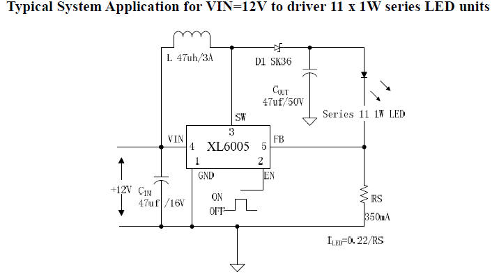
LED driver circuit diagram VIN=12V
to driver 11 x 1W series LED units
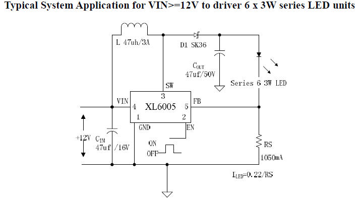
LED driver circuit diagram
VIN>=12V to driver 6 x 3W series LED units
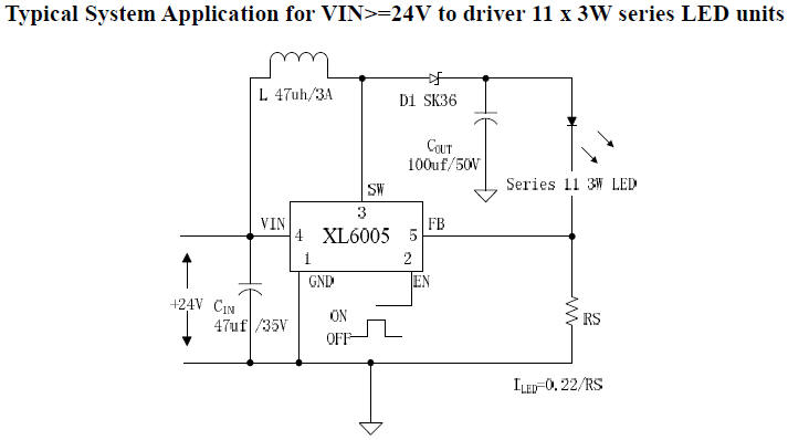
LED driver circuit diagram
VIN>=24V to driver 11 x 3W series LED units
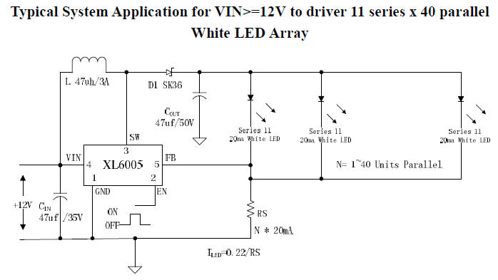
TLED driver circuit diagram VIN>=12V to driver 11
series x 40 parallel
White LED Array
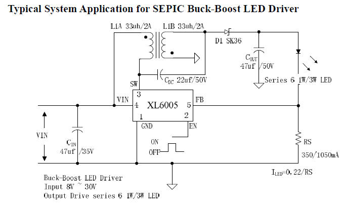
LED driver circuit diagram
SEPIC Buck-Boost LED Driver
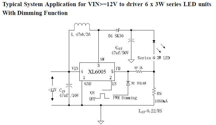
LED driver circuit diagram
VIN>=12V to driver 6 x 3W series LED units
With Dimming Function
Download source: 180KHz 60V 4A Switching Current
Boost LED Constant Current Driver
http://www.xlsemi.com/datasheet/XL6005%20datasheet.pdf
|
