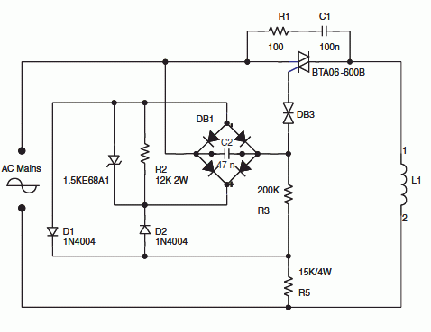
220V to 110 V step-down circuit
The schematic shows a 220V to 110V step-down circuit used to
approximately divide by two the rms voltage between the line input
and the inductive load (L1). C2 and R3 provide a turn-on delay of
approximately 7 ms.
The diode bridge, with diodes D1 and D2 and R2 resistor are used to
discharge C2 at each line zero voltage. This resets the voltage
charge at each new half line cycle, and keeps the same turn-on delay.
The Transil reduces the power dissipation through R3.
Synchronization by the mains voltage. 220/110 V step-down
circuit

|