| |
|
|
| |
DC to AC
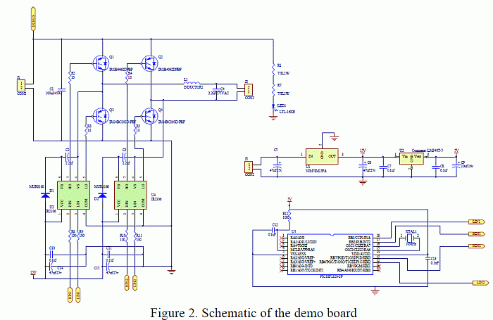
sine solar inverter IGBT 200V to 120V 500W schematic circuit
diagram schema


The purpose of a DC to AC inverter with IGBT transistors
is to convert DC
voltage to a pure sinusoidal output
voltage in applications such as UPS, solar inverter and
frequency converter.
This demo board is designed to operate without fan up to
500W.
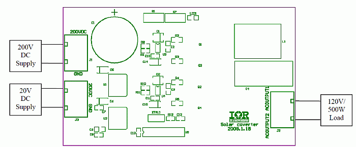
200V, 3A DC power supply
20V, 100 mA DC power supply
120V/500W load bank such as resistors, light bulbs or a
portable heater
Operation:
Always start the system by applying power to the +20V power
supply prior to applying
+200V DC bus. With a 120V/500W resistive load connected, the
output will be a
nominal 120V/60 Hz AC sinusoidal voltage as shown in Figure
3. This figure also shows
the output gate voltages across each IGBT showing 60 Hz
commutation and 20 kHz sine
PWM signals for low and high side devices, respectively.
|
|