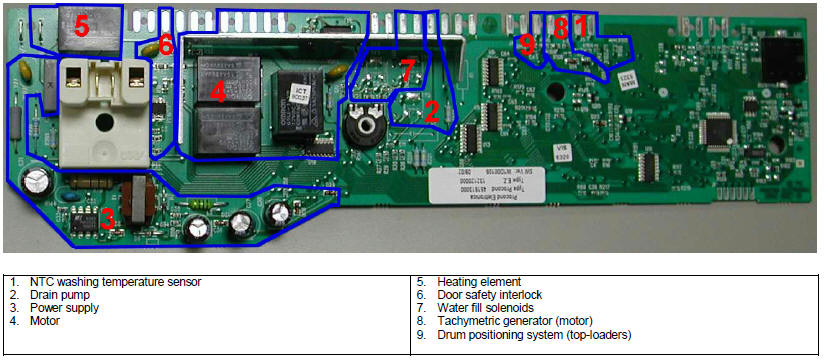
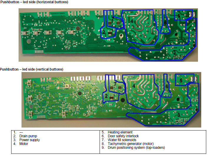
In case of burning on the main circuit board, check
that the problem is not caused by another electrical component (short-circuits,
poor insulation, water leakage).
Refer to the figures below in order to identify the
component that might have caused the burning according to the
position of the burned area.
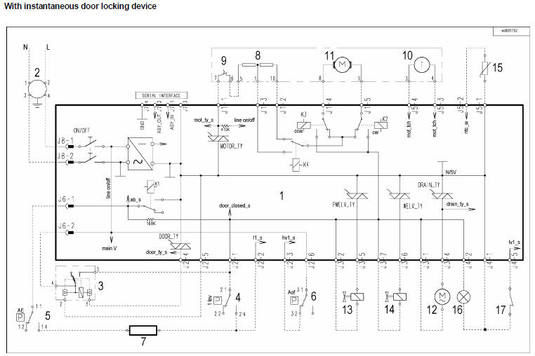
The circuit board shown below is the version with the greatest
number of components: other boards may not feature all these
components (relay K4 and buzzer).
|
Alarm |
Description |
Possible fault |
Action/Machine status |
Reset |
|
E00 |
No alarm |
|
E11 |
Difficulty in filling during wash phase |
Tap closed or water pressure insufficient; Drain hose
incorrectly positioned; Water fill solenoid faulty; Leaks
from pressure switch hydraulic circuit; Pressure switch
faulty; Wiring faulty; Circuit board faulty. |
Cycle paused, door closed |
Start |
|
E13 |
Water leakage |
Drain hose incorrectly positioned; Water pressure
insufficient; Water fill solenoid faulty; Leaks or blockage
in pressure switch hydraulic circuit; Pressure switch faulty;
Circuit board faulty. |
Cycle paused, door closed |
Start |
|
E21 |
Difficulties in draining |
Drain hose kinked/blocked/incorrectly positioned; Drain
filter clogged or dirty; Drain pump faulty; Pressure switch
faulty;
Wiring faulty; Circuit board faulty; Current leakage from
heating element to ground. |
Cycle paused |
Start |
|
E23 |
Drain pump triac faulty |
Drain pump faulty; Wiring faulty; Circuit board faulty. |
Safety drain - Cycle stopped, door open |
Selector on “0” |
|
E24 |
Problems with «sensing» of drain pump triac |
Circuit board faulty. |
Safety drain – Cycle stopped, door released |
Selector on “0” |
|
E33 |
Incongruence between contact closure of anti-
boiling and 1st level of pressure switch |
Pressure switch faulty; Current leakage from heating
element to ground; Heating element; Wiring faulty; Circuit
board faulty. |
Safety drain - Cycle stopped, door open |
Selector on “0” |
|
E35 |
Water overflow |
Water fill solenoid faulty; Leaks from pressure switch
hydraulic circuit; Pressure switch faulty; Wiring faulty;
Circuit board faulty. |
Cycle blocked, door closed. Safety drain.
Drain pump (sequence 5 min. ON - 5 min.
OFF) |
Selector on “0” |
|
E36 |
«sensing» circuit of anti-boiling pressure switch
faulty |
Circuit board faulty. |
Cycle blocked, door closed |
Selector on “0” |
|
E37 |
«sensing» circuit of 1st level faulty |
Circuit board faulty. |
Cycle blocked, door closed |
Selector on “0” |
|
E39 |
HV «sensing» circuit of anti-flooding pressure
switch faulty |
Circuit board faulty. |
Cycle blocked, door closed |
Selector on “0” |
|
E41 |
Door open |
Door safety interlock faulty; Wiring faulty;
Circuit board faulty. |
Cycle paused |
Start |
|
E42 |
Problems with aperture of door |
Door safety interlock faulty; Wiring faulty;
Circuit board faulty |
Cycle paused |
Start or Selector
on “0” |
|
E43 |
Power triac on door interlock faulty |
Door safety interlock faulty; Wiring faulty;
Circuit board faulty. |
Safety drain, door released |
Selector on “0” |
|
E44 |
Door interlock «sensing» faulty |
Circuit board faulty. |
Safety drain, door released |
Selector on “0” |
|
E45 |
«sensing» on door interlock triac faulty |
Circuit board faulty. |
Safety drain, door released |
Selector on “0” |
|
E51 |
Motor power triac short-circuited |
Circuit board faulty;
Current leakage from motor or wiring. |
Cycle blocked, door closed (after 5 attempts in diagnostics
or immediate during selection) |
Selector on “0” |
|
E52 |
No signal from motor tachimetric generator |
Motor faulty; Wiring faulty;
Circuit board faulty. |
Cycle blocked, door closed (after 5 attempts in diagnostics
or immediate during selection) |
Selector on “0” |
|
E53 |
«sensing» circuit on motor triac faulty |
Circuit board faulty. |
Cycle blocked |
Selector on “0” |
|
E54 |
Motor relay contacts sticking |
Circuit board faulty;
Current leakage from motor or wiring. |
Cycle blocked, door closed (after 5 attempts in diagnostics
or immediate during selection) |
Selector on “0” |
|
E61 |
Insufficient heating during washing |
NTC sensor faulty; Heating element faulty; Wiring faulty;
Circuit board faulty. |
Heating phase skipped |
--- |
|
E62 |
Overheating during washing |
NTC sensor faulty; Heating element faulty; Wiring faulty;
Circuit board faulty. |
Safety drain (with cooling water fill) - Stop with door open |
Selector on “0” |
|
E66 |
Power relay for heating element faulty |
Circuit board faulty; Current leakage from heating element
or wiring to ground. |
Safety drain (with cooling water fill) - Stop with door open |
Selector on “0” |
|
E71 |
NTC washing sensor faulty |
NTC sensor faulty; Wiring faulty;
Circuit board faulty. |
Heating phase skipped |
--- |
|
E82 |
Error in reset position of selector |
Circuit board faulty. |
Cycle cancelled |
Selector on “0” |
|
E83 |
Error in reading selector position |
Configuration data incorrect; Circuit board faulty. |
During the cycle continues normally, switches off completely
during selection |
--- |
|
E93 |
Incorrect machine configuration |
Configuration data incorrect; Circuit board faulty. |
Appliance blocked |
Selector on “0” |
|
E94 |
Incorrect washing cycle configuration |
Configuration data incorrect; Circuit board faulty. |
Appliance blocked |
Selector on “0” |
|
E95 |
Communications error between microprocessor
and EEPROM |
Circuit board faulty. |
Appliance blocked |
Selector on “0” |
|
E96 |
Incongruence between hardware version and
configuration. |
Configuration data incorrect; Circuit board faulty. |
Appliance blocked |
Selector on “0” |
|
E97 |
Incongruence between programme selector and
cycle configuration |
Configuration data incorrect; Circuit board faulty. |
Appliance blocked |
Selector on “0” |
|
EB1 |
Power supply frequency of appliance incorrect |
Mains power supply problems (incorrect / interference);
Circuit board faulty. |
Cycle blocked until normal power supply
conditions are restored |
Selector on “0” |
|
EB2 |
Voltage too high |
Mains power supply problems (incorrect / interference);
Circuit board faulty. |
Cycle blocked until normal power supply
conditions are restored |
Selector on “0” |
|
EB3 |
Voltage too low |
Mains power supply problems (incorrect / interference);
Circuit board faulty. |
Cycle blocked until normal power supply
conditions are restored |
Selector on “0” |